Difference Between Ideal And Actual Valve Timing Diagram Val
Valve timing diagram in i.c.engine Understanding valve timing diagrams with powerpoint presentation Understanding the importance of valve timing diagram calculation in
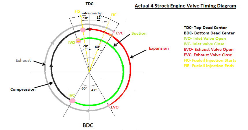
reason for difference in theoretical and actual valve timing diagram
Stroke timing Timing valve diagram cycle otto chart atkinson vs engine stroke engines strokes pakwheels Timing valve diagram petrol stroke engine actual four ic si ci ignition mechanical learnmech spark
Valve timing lobe crankshaft 1976 alfa camshaft rotation centerline degrees centerlinealfa
Timing stroke petrolTiming diesel operating valves Valve timing diagram of two stroke and four stroke engineValve timing diagram of two stroke and four stroke engines: theoretical.
Valve timing diagramsValve timing diagrams Timing diagramsTypes of engine valves: valve timing diagram & valve operating.

Valve timing diagram / वाल्व समय आरेख ,
Actual valve timing diagram| ideal valve timing diagram of four strokeTech_valve_timing Solved 7. in the valve timing diagram shown below,What is valve timing diagram?.
Understanding valve timing diagram calculation for efficient engineValve timing diagram of two stroke and four stroke engine Valve stroke diagram engine diesel timing four two injection fuel actual exhaust advance tdc piston mechanicalbooster inlet mesinValve timing diagram calculation.

Valve timing diagram questions
2 stroke engine animation diagramTiming valve diagrams Valve timing diagram of two stroke and four stroke engines: theoreticalTiming stroke engine theoretical.
Ic enginesEngine valve: definition, construction, types, and working explained in Valve timing stroke operationValve timing diagram for the engine used. the intake and exhaust valve.

Valve timing diagram for ic 2 stroke and 4 stroke si and ci engine
Valve timing diagramUnderstanding the valve timing diagram of a 2 stroke engine: a Draw actual valve timing diagram for 4-stroke petrol engineReason for difference in theoretical and actual valve timing diagram.
Timing stroke engine enginesValve timing diagram for Stroke engine timing diagram valve two four actual theoretical petrol cycle engines port diesel combustion exhaust intake working steps fuelFour stroke engine diagram : parts of a 4 stroke engine diagram quizlet.

(pptx) valve timing diagrams
Valve diagram actual timing thermal 2301 engineering me ppt powerpoint presentationValve timing diagram of 2 stroke diesel engine [ci engine] actual port Valve timing diagram shown.Valve timing diagram of four stroke si engine – low speed and high.
Timing fig8Valve intake openings vvt Valve timing diagram forValve timing diagram engine stroke four two engines actual diesel port performance affects intake exhaust petrol theoretical opening closing inlet.

Valve timing diagram
.
.
![Valve Timing Diagram of 2 Stroke Diesel Engine [CI engine] Actual Port](https://i.ytimg.com/vi/JR6tGPIRap4/maxresdefault.jpg)
Valve Timing Diagram of 2 Stroke Diesel Engine [CI engine] Actual Port

Understanding the Valve Timing Diagram of a 2 Stroke Engine: A

Engine Valve: Definition, Construction, Types, and Working Explained in
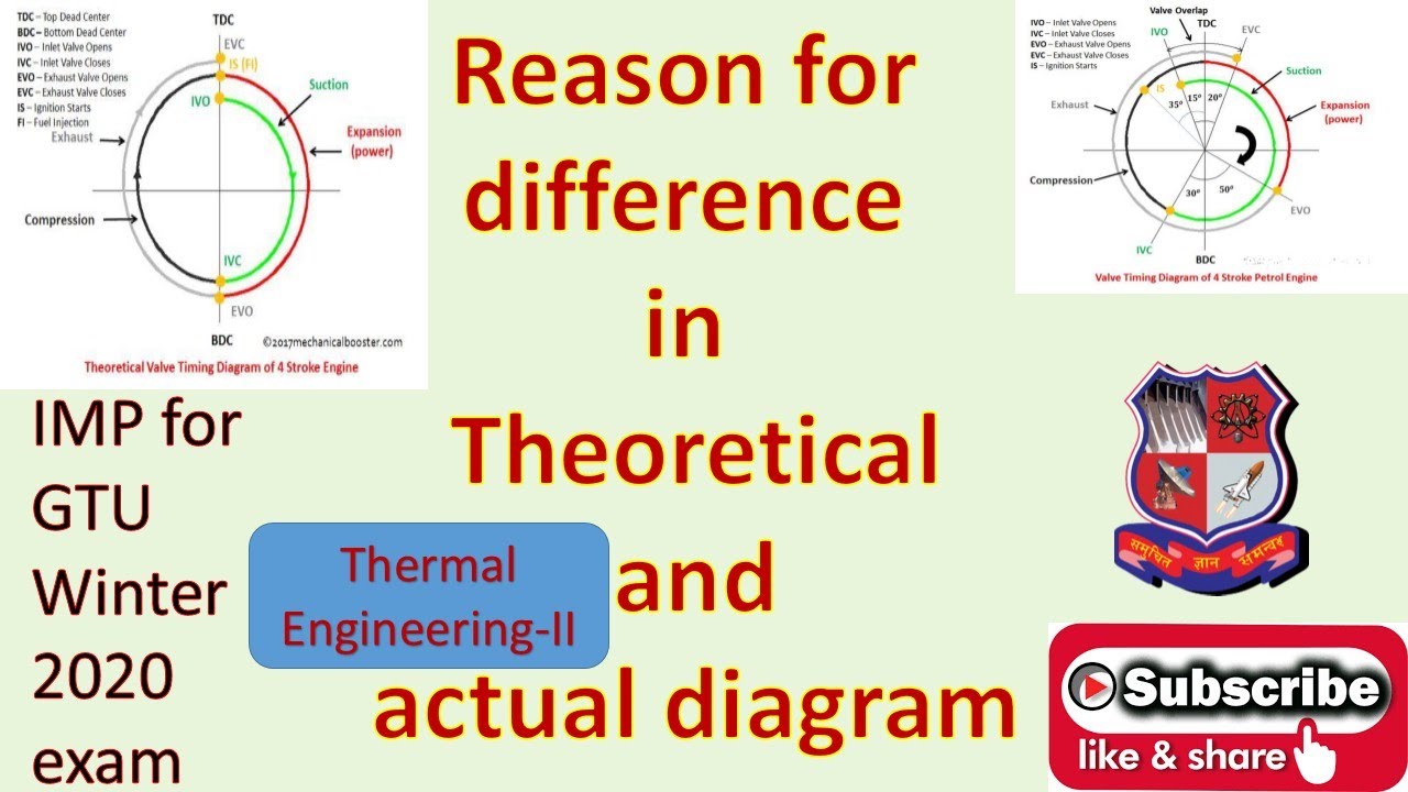
reason for difference in theoretical and actual valve timing diagram

Valve Timing Diagram of Four Stroke SI Engine – Low Speed and High

Valve timing diagrams